


articles
Vector Graphics on the GPU
Dec 5, 10:05 pm
I am quite a fan of vector graphics, and think they look absolutely amazing in motion, but there is no native support on desktop GPUs for drawing Bézier curves. However, obviously that doesn't stop a graphics programmer! The two most popular ways to draw Bézier curves on a GPU are outlined below:
Method 1
A trivial method to draw Bézier curves would be to simply calculate the curves on the CPU, then tessellate the points. This, although extremely easy to implement, has many drawbacks. First and foremost, calculating a Bézier curve and then tessellating a large cloud of points is a slow process when done more than once a frame in a realtime simulation, such as a game. Furthermore, when zooming in on a vector graphic, the quality is lost and the vector fun is spoiled by unsightly straight lines where there should be curves. The smaller the steps employed when calculating the approximate of the Bézier curve also leads to framerate and memory issues.
To demonstrate the quality problem of this method, take a look at this image where the steps, or s, are at 3 and 6 in comparison to the original curve:

Notice the sharp lines that approximate the curve and the extra points required to represent it. Furthermore, if a constant step value is used for each curve in an image, longer curves will suffer much more of a loss in quality than shorter curves.
Not only does it look bad close up, but it adds overhead when storing the data. For a step value of 6, an extra two points will be generated for each quadratic curve. This may not seem like much, but it adds up quite considerably the more curves an object has. In a game I implemented this naive curve drawing algorithm in, there were some ~50,000 curves drawn per frame at best, and I used a quality setting in the range of 16 to 24. That's 13 extra points per curve at the minimum. I also targeted hardware that lacked support for vertex buffer objects and shaders, so I had to send the geometry to the graphics card every frame.
Method 2
(This method is much better explained in Loop and Blinn's excellent paper found here, but I will give a brief and simple summary for quadratic curves.)
By making using of the programmable graphics pipeline, drawing quadratic curves is rather simple; all one needs to do is solve the inequality u2 - v < 0 in a fragment shader. Now, the question is, what are these uv values? In order to find out, take a look at this informative picture:
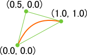
Each vertex of the triangle stores two points: the position and the uv values. The first point of the triangle is the starting point and has the uv pair of (0, 0). The second is the control point and has the uv pair of (0.5, 0). The third and last is the ending point, which has the uv pair of (1, 1).
To provide some code, here is an example vertex shader and the corresponding fragment shader that plots the point on the screen:
quadratic.vert:
#version 150

uniform mat4 game_Projection;
uniform mat4 game_View;

in vec2 game_Position; // Vertex position
in vec2 game_ControlPoint; // UV value pair

smooth out vec2 frag_ControlPoint;

void main()
{
	gl_Position = game_Projection * game_View *
		vec4(game_Position, 0, 1);

	frag_ControlPoint = game_ControlPoint;
}
quadratic.frag:
#version 150

smooth in vec2 frag_ControlPoint; // UV value pair

out vec4 game_FragColor; // Output color

void main()
{
	float u = frag_ControlPoint.s;
	float v = frag_ControlPoint.t;

	// If the inequality evaluates to false, then this fragment
	// is within the curve. Otherwise, the fragment is outside
	// the curve, so discard it.
	if ((u * u) - v > 0)
		discard;

	game_FragColor = vec4(1, 0, 0, 1);
}
This method has much over the first. Only slightly more geometry is needed (enough to fill the inside of the shape and nothing more). Quality is never compromised, because the uv value pair is interpolated over the screen, just like texture coordinates. Lastly, tessellation of such points is several times quicker because there are considerably less points to tessellate.
Example
Here is an example of the second method as described by Loop and Blinn:
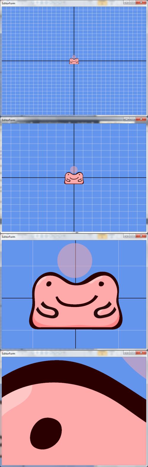
Notice the quality, from the first image to the last. This would not be possible at a steady framerate with the first method.
Conclusion
There is no doubt that the method presented by Loop and Blinn is a large step ahead of the first method. Quality, speed, and memory are all much improved over crude approximation using the CPU. Loop and Blinn's method only requires decently recent hardware (simply a programmable vertex/fragment pipeline) in comparison to the CPU method, but that cost is negligible when considering how much better and more efficient their method is.
Future Articles on Vector Graphics
I intend to post two more articles about vector graphics in the near future. The first article will concern a way to take advantage of the stencil buffer to allow complex polygons, and similarly, a way to use the stencil buffer in order to fill a shape. On the other hand, the second article will discuss rigging and applying a skeletal animation to a vector graphic. Depending on how soon I am ready to deploy Algae for public consumption, these articles may come with sample programs! 'Til then, see ya.